A boiling water reactor (BWR) is a type of light-water nuclear reactor developed by the General Electric Company in the mid 1950s.

1.Reactor pressure vessel 2.Fuel rods 3. Control rod 4.Circulating pump 5.Control rod drive 6.Fresh steam 7. Feedwater 8.High pressure turbine 9.Low pressure turbine 10.Generator 11.Exciter 12.Condenser 13.Cooling water 14.Preheater 15.Feedwater pump 16. Cooling water pump 17.Concrete shield
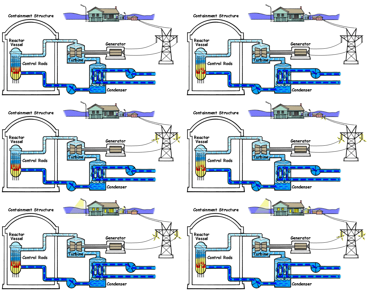
The above diagram shows BWR and its main parts.The BWR is characterized by two-phase fluid flow (water and steam) in the upper part of the reactor core. Light water (i.e., common distilled water) is the working fluid used to conduct heat away from the nuclear fuel. The water around the fuel elements also "thermalizes" neutrons, i.e., reduces their kinetic energy, which is necessary to improve the probability of fission of fissile fuel. Fissile fuel material, such as the U-235 and Pu-239 isotopes, have large capture cross sections for thermal neutrons.
In a boling water reactor, light water (H2O) plays the role of moderator and coolant, as well. In this case the steam is generted in the reactor it self.As you can see in the diagrm feed water enters the reactor pressure vessel at the bottom and takes up the heat generated due to fission of fuel (fuel rods) and gets converted in to steam.
Part of the water boils away in the reactor pressure vessel, thus a mixture of water and steam leaves the reactor core. The so generated steam directly goes to the turbine, therefore steam and moisture must be separated (water drops in steam can damage the turbine blades). Steam leaving the turbine is condensed in the condenser and then fed back to the reactor after preheating. Water that has not evaporated in the reactor vessel accumulates at the bottom of the vessel and mixes with the pumped back feedwater.
Since boiling in the reactor is allowed, the pressure is lower than that of the PWRs: it is about 60 to 70 bars. The fuel is usually uranium dioxide. Enrichment of the fresh fuel is normally somewhat lower than that in a PWR. The advantage of this type is that - since this type has the simplest construction - the building costs are comparatively low. 22.5% of the total power of presently operating nuclear power plants is given by BWRs.
Feedwater Inside of a BWR reactor pressure vessel (RPV), feedwater enters through nozzles high on the vessel, well above the top of the nuclear fuel assemblies (these nuclear fuel assemblies constitute the "core") but below the water level. The feedwater is pumped into the RPV from the condensers located underneath the low pressure turbines and after going through feedwater heaters that raise its temperature using extraction steam from various turbine stages.
The feedwater enters into the downcomer region and combines with water exiting the water separators. The feedwater subcools the saturated water from the steam separators. This water now flows down the downcomer region, which is separated from the core by a tall shroud. The water then goes through either jet pumps or internal recirculation pumps that provide additional pumping power (hydraulic head). The water now makes a 180 degree turn and moves up through the lower core plate into the nuclear core where the fuel elements heat the water. When the flow moves out of the core through the upper core plate, about 12 to 15% of the flow by volume is saturated steam.
The heating from the core creates a thermal head that assists the recirculation pumps in recirculating the water inside of the RPV. A BWR can be designed with no recirculation pumps and rely entirely on the thermal head to recirculate the water inside of the RPV. The forced recirculation head from the recirculation pumps is very useful in controlling power, however. The thermal power level is easily varied by simply increasing or decreasing the speed of the recirculation pumps.
The two phase fluid (water and steam) above the core enters the riser area, which is the upper region contained inside of the shroud. The height of this region may be increased to increase the thermal natural recirculation pumping head. At the top of the riser area is the water separator. By swirling the two phase flow in cyclone separators, the steam is separated and rises upwards towards the steam dryer while the water remains behind and flows horizontally out into the downcomer region. In the downcomer region, it combines with the feedwater flow and the cycle repeats.
The saturated steam that rises above the separator is dried by a chevron dryer structure. The steam then exists the RPV through four main steam lines and goes to the turbine.
Control systems
Reactor power is controlled via two methods: by inserting or withdrawing control rods and by changing the water flow through the reactor core.
Positioning (withdrawing or inserting) control rods is the normal method for controlling power when starting up a BWR. As control rods are withdrawn, neutron absorption decreases in the control material and increases in the fuel, so reactor power increases. As control rods are inserted, neutron absorption increases in the control material and decreases in the fuel, so reactor power decreases. Some early BWRs and the proposed ESBWR designs use only natural ciculation with control rod positioning to control power from zero to 100% because they do not have reactor recirculation systems.
Changing (increasing or decreasing) the flow of water through the core is the normal and convenient method for controlling power. When operating on the so-called "100% rod line," power may be varied from approximately 70% to 100% of rated power by changing the reactor recirculation system flow by varying the speed of the recirculation pumps. As flow of water through the core is increased, steam bubbles ("voids") are more quickly removed from the core, the amount of liquid water in the core increases, neutron moderation increases, more neutrons are slowed down to be absorbed by the fuel, and reactor power increases. As flow of water through the core is decreased, steam voids remain longer in the core, the amount of liquid water in the core decreases, neutron moderation decreases, fewer neutrons are slowed down to be absorbed by the fuel, and reactor power decreases.
Steam Turbines
Steam produced in the reactor core passes through steam separators and dryer plates above the core and then directly to the turbine, which is part of the reactor circuit. Because the water around the core of a reactor is always contaminated with traces of radionuclides, the turbine must be shielded during normal operation, and radiological protection must be provided during maintenance. The increased cost related to operation and maintenance of a BWR tends to balance the savings due to the simpler design and greater thermal efficiency of a BWR when compared with a PWR. Most of the radioactivity in the water is very short-lived (mostly N-16, with a 7 second half life), so the turbine hall can be entered soon after the reactor is shut down.
Safety Like the pressurized water reactor, the BWR reactor core continues to produce heat from radioactive decay after the fission reactions have stopped, making nuclear meltdown possible in the event that all safety systems have failed and the core does not receive coolant. Also like the pressurized water reactor, a boiling-water reactor has a negative void coefficient, that is, the thermal output decreases as the proportion of steam to liquid water increases inside the reactor. However, unlike a pressurized water reactor which contains no steam in the reactor core, a sudden increase in BWR steam pressure (caused, for example, by a blockage of steam flow from the reactor) will result in a sudden decrease in the proportion of steam to liquid water inside the reactor. The increased ratio of water to steam will lead to increased neutron moderation, which in turn will cause an increase in the power output of the reactor. Because of this effect in BWRs, operating components and safety systems are designed to ensure that no credible, postulated failure can cause a pressure and power increase that exceeds the safety systems' capability to quickly shutdown the reactor before damage to the fuel or to components containing the reactor coolant can occur.
In the event of an emergency that disables all of the safety systems, each reactor is surrounded by a containment building designed to seal off the reactor from the environment.
 Comparison with other reactors Light water is ordinary water. In comparison, some other water-cooled reactor types use heavy water. In heavy water, the deuterium isotope of hydrogen replaces the common hydrogen atoms in the water molecules (D2O instead of H2O, molecular weight 20 instead of 18).
The Pressurized Water Reactor (PWR) was the first type of light-water reactor developed because of its application to submarine propulsion. The civilian motivation for the BWR is reducing costs for commercial applications through design simplification and lower pressure components. In naval reactors, BWR designs are used when natural circulation is specified for its quietness. The description of BWRs below describes civilian reactor plants in which the same water used for reactor cooling is also used in the Rankine cycle turbine generators. A Naval BWR is designed like a PWR that has both primary and secondary loops.
In contrast to the pressurized water reactors that utilize a primary and secondary loop, in civilian BWRs the steam going to the turbine that powers the electrical generator is produced in the reactor core rather than in steam generators or heat exchangers. There is just a single circuit in a civilian BWR in which the water is at lower pressure (about 75 times atmospheric pressure) compared to a PWR so that it boils in the core at about 285°C. The reactor is designed to operate with steam comprising 12–15% of the volume of the two-phase coolant flow (the "void fraction") in the top part of the core, resulting in less moderation, lower neutron efficiency and lower power density than in the bottom part of the core. In comparison, there is no significant boiling allowed in a PWR because of the high pressure maintained in its primary loop (about 158 times atmospheric pressure).
Advantages

1.Reactor pressure vessel 2.Fuel rods 3. Control rod 4.Circulating pump 5.Control rod drive 6.Fresh steam 7. Feedwater 8.High pressure turbine 9.Low pressure turbine 10.Generator 11.Exciter 12.Condenser 13.Cooling water 14.Preheater 15.Feedwater pump 16. Cooling water pump 17.Concrete shield
The above diagram shows BWR and its main parts.The BWR is characterized by two-phase fluid flow (water and steam) in the upper part of the reactor core. Light water (i.e., common distilled water) is the working fluid used to conduct heat away from the nuclear fuel. The water around the fuel elements also "thermalizes" neutrons, i.e., reduces their kinetic energy, which is necessary to improve the probability of fission of fissile fuel. Fissile fuel material, such as the U-235 and Pu-239 isotopes, have large capture cross sections for thermal neutrons.
In a boling water reactor, light water (H2O) plays the role of moderator and coolant, as well. In this case the steam is generted in the reactor it self.As you can see in the diagrm feed water enters the reactor pressure vessel at the bottom and takes up the heat generated due to fission of fuel (fuel rods) and gets converted in to steam.
Part of the water boils away in the reactor pressure vessel, thus a mixture of water and steam leaves the reactor core. The so generated steam directly goes to the turbine, therefore steam and moisture must be separated (water drops in steam can damage the turbine blades). Steam leaving the turbine is condensed in the condenser and then fed back to the reactor after preheating. Water that has not evaporated in the reactor vessel accumulates at the bottom of the vessel and mixes with the pumped back feedwater.
Since boiling in the reactor is allowed, the pressure is lower than that of the PWRs: it is about 60 to 70 bars. The fuel is usually uranium dioxide. Enrichment of the fresh fuel is normally somewhat lower than that in a PWR. The advantage of this type is that - since this type has the simplest construction - the building costs are comparatively low. 22.5% of the total power of presently operating nuclear power plants is given by BWRs.
Feedwater Inside of a BWR reactor pressure vessel (RPV), feedwater enters through nozzles high on the vessel, well above the top of the nuclear fuel assemblies (these nuclear fuel assemblies constitute the "core") but below the water level. The feedwater is pumped into the RPV from the condensers located underneath the low pressure turbines and after going through feedwater heaters that raise its temperature using extraction steam from various turbine stages.
The feedwater enters into the downcomer region and combines with water exiting the water separators. The feedwater subcools the saturated water from the steam separators. This water now flows down the downcomer region, which is separated from the core by a tall shroud. The water then goes through either jet pumps or internal recirculation pumps that provide additional pumping power (hydraulic head). The water now makes a 180 degree turn and moves up through the lower core plate into the nuclear core where the fuel elements heat the water. When the flow moves out of the core through the upper core plate, about 12 to 15% of the flow by volume is saturated steam.
The heating from the core creates a thermal head that assists the recirculation pumps in recirculating the water inside of the RPV. A BWR can be designed with no recirculation pumps and rely entirely on the thermal head to recirculate the water inside of the RPV. The forced recirculation head from the recirculation pumps is very useful in controlling power, however. The thermal power level is easily varied by simply increasing or decreasing the speed of the recirculation pumps.
The two phase fluid (water and steam) above the core enters the riser area, which is the upper region contained inside of the shroud. The height of this region may be increased to increase the thermal natural recirculation pumping head. At the top of the riser area is the water separator. By swirling the two phase flow in cyclone separators, the steam is separated and rises upwards towards the steam dryer while the water remains behind and flows horizontally out into the downcomer region. In the downcomer region, it combines with the feedwater flow and the cycle repeats.
The saturated steam that rises above the separator is dried by a chevron dryer structure. The steam then exists the RPV through four main steam lines and goes to the turbine.
Control systems
Reactor power is controlled via two methods: by inserting or withdrawing control rods and by changing the water flow through the reactor core.
Positioning (withdrawing or inserting) control rods is the normal method for controlling power when starting up a BWR. As control rods are withdrawn, neutron absorption decreases in the control material and increases in the fuel, so reactor power increases. As control rods are inserted, neutron absorption increases in the control material and decreases in the fuel, so reactor power decreases. Some early BWRs and the proposed ESBWR designs use only natural ciculation with control rod positioning to control power from zero to 100% because they do not have reactor recirculation systems.
Changing (increasing or decreasing) the flow of water through the core is the normal and convenient method for controlling power. When operating on the so-called "100% rod line," power may be varied from approximately 70% to 100% of rated power by changing the reactor recirculation system flow by varying the speed of the recirculation pumps. As flow of water through the core is increased, steam bubbles ("voids") are more quickly removed from the core, the amount of liquid water in the core increases, neutron moderation increases, more neutrons are slowed down to be absorbed by the fuel, and reactor power increases. As flow of water through the core is decreased, steam voids remain longer in the core, the amount of liquid water in the core decreases, neutron moderation decreases, fewer neutrons are slowed down to be absorbed by the fuel, and reactor power decreases.
Steam Turbines
Steam produced in the reactor core passes through steam separators and dryer plates above the core and then directly to the turbine, which is part of the reactor circuit. Because the water around the core of a reactor is always contaminated with traces of radionuclides, the turbine must be shielded during normal operation, and radiological protection must be provided during maintenance. The increased cost related to operation and maintenance of a BWR tends to balance the savings due to the simpler design and greater thermal efficiency of a BWR when compared with a PWR. Most of the radioactivity in the water is very short-lived (mostly N-16, with a 7 second half life), so the turbine hall can be entered soon after the reactor is shut down.
Safety Like the pressurized water reactor, the BWR reactor core continues to produce heat from radioactive decay after the fission reactions have stopped, making nuclear meltdown possible in the event that all safety systems have failed and the core does not receive coolant. Also like the pressurized water reactor, a boiling-water reactor has a negative void coefficient, that is, the thermal output decreases as the proportion of steam to liquid water increases inside the reactor. However, unlike a pressurized water reactor which contains no steam in the reactor core, a sudden increase in BWR steam pressure (caused, for example, by a blockage of steam flow from the reactor) will result in a sudden decrease in the proportion of steam to liquid water inside the reactor. The increased ratio of water to steam will lead to increased neutron moderation, which in turn will cause an increase in the power output of the reactor. Because of this effect in BWRs, operating components and safety systems are designed to ensure that no credible, postulated failure can cause a pressure and power increase that exceeds the safety systems' capability to quickly shutdown the reactor before damage to the fuel or to components containing the reactor coolant can occur.
In the event of an emergency that disables all of the safety systems, each reactor is surrounded by a containment building designed to seal off the reactor from the environment.
 Comparison with other reactors Light water is ordinary water. In comparison, some other water-cooled reactor types use heavy water. In heavy water, the deuterium isotope of hydrogen replaces the common hydrogen atoms in the water molecules (D2O instead of H2O, molecular weight 20 instead of 18).
 The Pressurized Water Reactor (PWR) was the first type of light-water reactor developed because of its application to submarine propulsion. The civilian motivation for the BWR is reducing costs for commercial applications through design simplification and lower pressure components. In naval reactors, BWR designs are used when natural circulation is specified for its quietness. The description of BWRs below describes civilian reactor plants in which the same water used for reactor cooling is also used in the Rankine cycle turbine generators. A Naval BWR is designed like a PWR that has both primary and secondary loops.
In contrast to the pressurized water reactors that utilize a primary and secondary loop, in civilian BWRs the steam going to the turbine that powers the electrical generator is produced in the reactor core rather than in steam generators or heat exchangers. There is just a single circuit in a civilian BWR in which the water is at lower pressure (about 75 times atmospheric pressure) compared to a PWR so that it boils in the core at about 285°C. The reactor is designed to operate with steam comprising 12–15% of the volume of the two-phase coolant flow (the "void fraction") in the top part of the core, resulting in less moderation, lower neutron efficiency and lower power density than in the bottom part of the core. In comparison, there is no significant boiling allowed in a PWR because of the high pressure maintained in its primary loop (about 158 times atmospheric pressure).
Advantages
- The reactor vessel and associated components operate at a substantially lower pressure (about 75 times atmospheric pressure) compared to a PWR (about 158 times atmospheric pressure).
- Pressure vessel is subject to significantly less irradiation compared to a PWR, and so does not become as brittle with age.
- Operates at a lower nuclear fuel temperature.
- Fewer components due to no steam generators and no pressurizer vessel. (Older BWRs have external recirculation loops, but even this piping is eliminated in modern BWRs, such as the ABWR.)
- Lower risk (probability) of a rupture causing loss of coolant compared to a PWR, and lower risk of a severe accident should such a rupture occur. This is due to fewer pipes, fewer large diameter pipes, fewer welds and no steam generator tubes.
- Measuring the water level in the pressure vessel is the same for both normal and emergency operations, which results in easy and intuitive assessment of emergency conditions.
- Can operate at lower core power density levels using natural circulation without forced flow.
- A BWR may be designed to operate using only natural circulation so that recirculation pumps are eliminated entirely. (The new ESBWR design uses natural circulation.)
- Complex operational calculations for managing the utilization of the nuclear fuel in the fuel elements during power production due to "two phase fluid flow" (water and steam) in the upper part of the core (less of a factor with modern computers). More incore nuclear instrumentation is required.
- Much larger pressure vessel than for a PWR of similar power, with correspondingly higher cost. (However, the overall cost is reduced because a modern BWR has no main steam generators and associated piping.)
- Contamination of the turbine by fission products.
- Shielding and access control around the steam turbine are required during normal operations due to the radiation levels arising from the steam entering directly from the reactor core. Additional precautions are required during turbine maintenance activities compared to a PWR.
- Control rods are inserted from below for current BWR designs. There are two available hydraulic power sources that can drive the control rods into the core for a BWR under emergency conditions. There is a dedicated high pressure hydraulic accumulator and also the pressure inside of the reactor pressure vessel available to each control rod. Either the dedicated accumulator (one per rod) or reactor pressure is capable of fully inserting each rod. Most other reactor types use top entry control rods that are held up in the withdrawn position by electromagnets, causing them to fall into the reactor by gravity if power is lost.


