Electrical power is supplied by a 12 volt, direct current system. The system includes a
12 volt 45 ampere alternator, regulator and 35 ampere hour battery to produce electrical power.
The battery is located in a sealed box aft of the baggage compartment. On the right side of the
fuselage near the battery is an external power receptacle enabling the use of an automotive
battery or external battery charger assist for starting or charging. The aircraft Master
Switch must be on for the external power relay to be energized to provide power to the aircraft
battery and electrical system.
A dual volt / amp meter indicates system performance. The gauge is designed so that
normal operation is indicated with both needles at or above level. Charging is indicated by a
positive ammeter reading and a voltage between 13 and 14.5 volts.
normal operation is indicated with both needles at or above level. Charging is indicated by a
positive ammeter reading and a voltage between 13 and 14.5 volts.
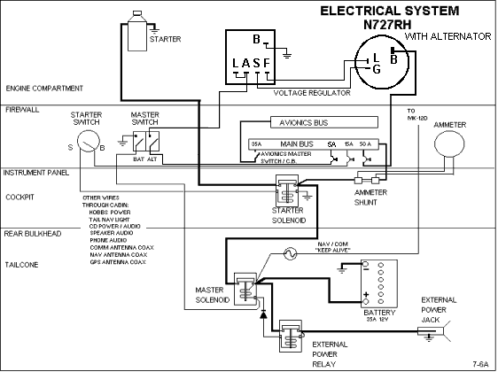
The split BAT / ALT Master switch "BAT" side energizes the master solenoid to provide
power to the main bus and lower row of circuit breakers. The "ALT" side of the switch energizes
the alternator field turning the alternator on to enable it to recharge the battery. The AVIONICS
MASTER switch / circuit breaker energizes the upper row of circuit breakers providing power to
the avionics. This switch is normally off for engine start. The engine starter solenoid is
located near the base of the copilot's control stick and is activated by the magneto key switch.
The circuit breakers automatically break the electrical circuit if an overload should
occur. To reset the circuit breaker simply push in the reset button. It may be necessary to
allow approximately two minutes for cooling before resetting a circuit breaker. Corrective
action should be taken in the event of continual circuit breaker popping or a circuit breaker
that will not stay reset. It is possible to manually trip a breaker by pulling out on the reset
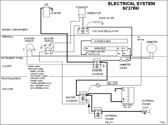
Electrical System Schematic
Current schematic with alternator
Former schematic with generator

button.
No comments:
Post a Comment