Tuesday, September 11, 2012

Installation time reduced by half


GE's ElfaPlus Fixwell MCBs and RCCBs (residual current circuit breakers) are the latest additions to the ElfaPlus range and have been designed to reduce installation time to the absolute minimum.

The Fixwell system can reduce installation time by 50% compared to using a manual screwdriver and 30% faster than with an electrical screwdriver.  Now it can all be done with the push of a button
Fixwell offers ‘plug and play’ tool-free installation.  Thanks to the design of the installation clamps, the cable is instantly and permanently fitted.  The tightening of the contact screws is finally a thing of the past.  Even the connection of MCBs and RCCBs to each other is significantly simplified by use of a busbar that is plugged in without screws.
Fixwell is compatible with the complete ElfaPlus range and has been specifically developed for the residential and commercial sector.

Homac Flood-Seal Street Lighting Connectors


Thomas & Betts offers a comprehensive line of Homac® Flood-Seal® Street Lighting Connectors that provide safe, reliable and convenient street and highway lighting connections for breakaway and non-breakaway applications.
Homac® Flood-Seal® Street Lighting Connectors are available in breakaway and non-breakaway applications. Breakaway kits, used for lighting highways, offer a selection of in-line and Y-type connectors for both fused and non-fused connections. Fuses, or fuse links for neutrals, remain in the load side of the rubber housing to ensure that no energized system components are exposed. All breakaway selections are available as mechanical or compression connections.
Non-breakaway kits, used for parking lots and residential streets that typically do not require breakaway capability, are available in three types of connection: bare, with a drop-on cover insulated after completing the connection; encapsulated, with integral cover and protection from contact during installation; and watertight, which prevents contact with connection at all times, while keeping water out after installation. All non-breakaway street lighting kits are dual rated to accept both aluminum and copper conductors, and range taking to accommodate multiple wire services and reduce inventory. All are prefilled with oxide and require no taping.

Cooper Transformer Design Optimizes Overload Capacity


PEAK™ transformers from Cooper Power Systems are uniquely designed to manage increased loads and temporary overload capacity with a four time greater life expectancy when compared to mineral oil-filled transformer alternatives. Utilities are able to operate PEAK transformers beyond full rated load to at least 112 percent to more precisely size transformers based on unpredictable periods of peak demand.
Utilizing an advanced high-temperature insulation system—comprised of thermally upgraded kraft paper, an optimized core and coil design, and Envirotemp™ FR3™ dielectric fluid—a 75-degree Average Winding Rise (AWR) PEAK transformer results in a smaller footprint and lighter unit capable of the same ratings as a physically larger 65 AWR rated unit. PEAK transformers are filled with the biodegradable alternative to transformer oil, Envirotemp™ FR3™ dielectric fluid, a critical enabling technology which extends transformer life and raises fire ignition resistance. In addition, this soybean oil-based fluid creates a barrier against water at the surface of the insulation making the thermal kraft paper in the coil windings stronger and longer lasting. All of these attributes combine for a lower total cost of ownership verses comparable fluid-filled transformers.
“New technology has always driven changes in transformer design standards. In 1956, Cooper Power Systems was the first to design and sell the 65 AWR transformer. It wasn’t until 1964 that 65 AWR became the standard,” said Mark Thurman, president, Cooper Power Systems, a division of Cooper Industries plc (NYSE: CBE). “Today, our PEAK transformer is the next step in that evolution, and is driving the adoption of new standards. The proposedIEEE Std C57.154™-2012, covering the design, testing, and applications of transformers operating at elevated temperatures such as the PEAK transformer, is in its final approval process. It is expected to be released in the autumn of 2012.”
The capacity to overload PEAK transformers contributes to system reliability during peak periods, as they can be continuously operated at higher temperature and higher load without reducing the life of the transformer. In addition, when compared to traditional transformer operation at the same kVA rating, the PEAK transformer will be smaller and lighter. These units will use less material and fewer gallons of dielectric fluid resulting in a better value as well as lower related costs of handling and operating the larger transformers.

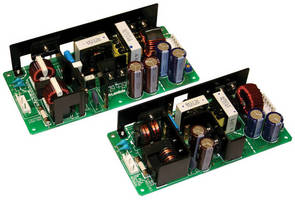
Compact 150/240 W Power Supplies offer up to 200% peak power.

Compact 150/240 W Power Supplies offer up to 200% peak power.
September 10, 2012 - Exhibiting 91% efficiency, TDK-Lambda ZWS-BP series has universal 85-264 Vac, 47-63 Hz input; can operate with DC input over 120-370 Vdc range; and offers outputs of 24, 36, or 48 Vdc. These open-frame, single-output power supplies, able to withstand 3 kVac input-to-output, have profiles from 1.46-1.65 in. and occupy 2.95 x 6.3 in. or 3.31 x 7.09 in. footprint. With convection cooling, RoHS-compliant products provide up to 150 or 240 W of output. 

DK-Lambda Unveils Compact 150 & 240 Watt Power Supplies with up to 200% Peak Power


Convection Cooled (No Fans) - 91% Efficient - For Industrial, ITE, Comms & Kiosk Applications

San Diego, CA - TDK Corporation announces the new TDK-Lambda ZWS-BP series of compact, open-frame, 150W and 240W power supplies. These single-output supplies have a low profile of 1.46" to 1.65" and compact footprints of 2.95" x 6.3" or 3.31" x 7.09". Moreover, these units can provide a peak output power of up to 200% (for motors, pumps, etc.), making them an ideal choice for applications in industrial, gaming, point-of-sale, test & measurement, LED signage, and communications equipment.

These new TDK-Lambda AC-DC supplies feature a universal 85-264Vac, 47-63Hz input, enabling them to be used anywhere in the world. The ZWS-BP is designed to withstand 3kVac, input-to-output. In addition, they can operate with a DC input over the range of 120-370Vdc. The supplies are available with an output voltage of 24V, 36V or 48Vdc and include an onboard output adjustment potentiometer.

With convection cooling (no fans required), these supplies provide up to 150 or 240-watts of output power. The operating temperature range is from -10°C to +70°C with derating above +50°C. The output is floating so it can be used as either a positive or a negative polarity. The power-saving efficiency is up to 91%. Standard features include overvoltage and overcurrent protections. Optional remote On/Off connections are available to allow for remote control of the supply.

The ZWS-BP series is an extension of the very successful ZWS series, which were employed in the high-definition Diamond Vision video displays that were built by Mitsubishi Electric and have been used to power some of the world's largest LED displays located at the Cowboys Stadium (Texas), Yankee Stadium (New York) and many other global sites. TDK-Lambda power supplies were selected for their long-term reliability and quality.

The ZWS-BP series feature global ITE and general purpose safety agency certifications per UL/CSA/EN60950-1, EN50178 (OV II), are CE Marked, meet the conducted and radiated EMI requirements of EN55011/EN55022-B, VCCI-B and FCC Class B, which is much tougher than Class A. These units are RoHS compliant and include a 5-year warranty, which is one of the longest-term warranties available in this power range.

Wednesday, August 15, 2012

Engine Electrical System

This is a computer drawing of the electrical system of the Wright brothers' 1903 
aircraft engine. This engine powered the first, heavier than air, self-propelled, mane
uverable, piloted aircraft; the Wright 1903 Flyer at Kitty Hawk, North Carolina, in 
December, 1903. To generate thrust for their aircraft, the brothers used twin, 
counter-rotating propellers at the rear of the aircraft. To turn the propellers, the 
brothers designed and built a water-cooled, gasoline powered, four-stroke, four c
ylinder,internal combustion engine.
Mechanical Operation


The figure at the top shows the major components of the electrical system on 

the Wright 1903 engine. In any internal combustion engine, fuel and oxygen are 
combined in a combustion process to produce the power to turn the crankshaft 
of the engine. The job of the electrical system is to provide the spark which initiates 
combustion.
Electrical power is generated by the magneto at the rear of the engine. The magneto 

relies on the physics principle ofelectrical inductance to produce electricity; 
when a wire is moved through a magnetic field an electrical current is inducedin 
the wire. The magneto has a large, U - shaped, permanent magnet at the top. 
Between the arms of the magnet, a wire is rotated on a shaft which is turned by 
the friction drive wheel rubbing on the engine flywheel. An electrical current is
 induced in the moving wire. The power to turn the magneto is provided by the
 running engine. The magneto is very similar to the alternator or generator on a 
modern automobile. The Wright brothers purchased their magneto and it 
provided a very modest 10 volts at 4 amps in operation. Two wires connect 
the magneto to the engine; a ground wire to the leg of the crankcase, and 
a power wire to the bus bar on the outside of the four combustion 
chambers of the engine.
On each combustion chamber, the bus bar conducts electricity to an ignition 

plug which is screwed through the wall of the chamber. The plug is insulated 
from the wall of the chamber. Inside the chamber, there is a contact 
switch which is movable. When the switch is closed, a circuit is created 
and electricity flows through the wires, bus bar and plug. When the switch 
is opened quickly, a spark is generated. You can see this effect if you
 pull the plug on an operating appliance at home. Spring levers 
mounted on the outside of the chamber are used to open and close
 the contact switch by an insulated shaft which passes through the wall 
of the combustion chamber. The spring levers are attached to the crankcase 
of the engine which is grounded to the magneto. The levers are activated 
by cams which turn on a cam shaft under the engine. The cam shaft is 
linked by gears to the exhaust valve cam shaft which is turned by the 
timing chain. The gears and cams insure that the contact switch is
 opened, and the ignition spark occurs at just the proper moment of 
the engine cycle. Here's a computer animation of the action of the levers 
and contact switch:


Computer animation of the Wright 1903 aircraft engine valves

In this animation, we have cut open cylinder #3 so that you can watch the motion of
the valves, cams, rocker arms, and electrical contacts and switches. The spring which
 moves the electrical contact
 inside cylinder #3 is partially hidden by the cylinder itself. The spring is barely visible
 behind the blue exhaust valve spring. You can better see the action of the electric cam
 and spring on the adjoining
cylinder #4 to the right. But notice that the timing of the motion of the switches
and valves is different between adjoining cylinders. On the animation, we have
cut the bus bar to allow us to see inside cylinder #3; the bar wraps around cylinder
 #3 in the same way that it wraps around cylinder #2 to the left.
How Does It Work?
To understand how the electrical system works, we have drawn a simplified
wiring diagram of the engine:


We have numbered the cylinders (and combustion chambers) from 1 to 4 going
 from the front of the engine to the back. The magneto, wires, contact switches,
and grounded cylinders produce an electrical circuit, which you have heard
about in school. This particular type of circuit is called a parallel circuit because
 there are parallel lines running through the four cylinders. The contact switch
on any cylinder can be opened or closed without affecting the neighboring cylinders.
 (If the cylinders were wired in series, opening any switch would cut the current to
ll the cylinders.)
Throughout nearly all of the cycle for a given cylinder, the contact switch is
held opened and no current flows through the system. But when the cam pushes
 the levers, the contact switch in one cylinder is initially closed which produces
a current of electricity from the magneto through the bus bar, switch, and
levers, to the crankcase and back to the magneto. This condition for cylinder
#1 is shown at the top of the figure. As the cam continues to move, the contact
switch is suddenly pulled open, as shown at the bottom of the figure. A small
spark occurs as the switch is opened (you can see this effect if you pull the
 plug on an operating lamp in your home.) Inside the combustion chamber, this
spark is used to ignite the fuel/air mixture at the end of the compression stroke.
The contact switch is kept open inside the cylinder until the next firing. The
opening of the switch is called an electrical break (of the circuit) and this firing
 technique is called a "make and break" system. The four cylinders of this engine
 fire one at a time in a firing order which is repeated. The brothers used a 1
 - 3 - 4 - 2 firing order to balance out the firings and make the engine run as smooth
 as possible.

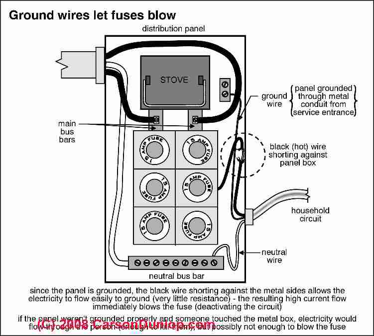
Ground wires let blow

Thursday, June 28, 2012

Electricity systems can cope with large-scale wind power


Research by TU Delft proves that Dutch power stations are able to cope at any time in the future with variations in demand for electricity and supply of wind power, as long as use is made of up-to-date wind forecasts. PhD candidate Bart Ummels also demonstrates that there is no need for energy storage facilities. Ummels will receive his PhD on this topic on Thursday 26 February. Wind is variable and can only partially be predicted. The large-scale use of wind power in the electricity system is therefore tricky. PhD candidate Bart Ummels MSc. investigated the consequences of using a substantial amount of wind power within the Dutch electricity system. He used simulation models, such as those developed by Dutch transmission system operator TenneT, to pinpoint potential problems (and solutions).
His results indicate that wind power requires greater flexibility from existing power stations. Sometimes larger reserves are needed, but more frequently power stations will have to decrease production in order to make room for wind-generated power. It is therefore essential to continually recalculate the commitment of power stations using the latest wind forecasts. This reduces potential forecast errors and enables wind power to be integrated more efficiently.
Ummels looked at wind power up to 12 GW, 8 GW of which at sea, which is enough to meet about one third of the Netherlands' demand for electricity. Dutch power stations are able to cope at any time in the future with variations in demand for electricity and supply of wind power, as long as use is made of up-to-date, improved wind forecasts. It is TenneT's task to integrate large-scale wind power into the electricity grid. Lex Hartman, TenneT's Director of Corporate Development: "in a joint effort, TU Delft and TenneT further developed the simulation model that can be used to study the integration of large-scale wind power. The results show that in the Netherlands we can integrate between 4 GW and 10 GW into the grid without needing any additional measures.
Surpluses
Ummels: 'Instead of the common question 'What do we do when the wind isn't blowing?', the more relevant question is 'Where do we put all the electricity if it is very windy at night?'. This is because, for instance, a coal-fired power station cannot simply be turned off. One solution is provided by the international trade in electricity, because other countries often can use the surplus. Moreover, a broadening of the 'opening hours' of the international electricity market benefits wind power. At the moment, utilities determine one day ahead how much electricity they intend to purchase or sell abroad. Wind power can be better used if the time difference between the trade and the wind forecast is smaller