Friday, June 19, 2020

Dahlander Dual Speed Motors


This type of motor has a short-circuited rotor and is mainly used in the operation of machines and fans, and as for the types of construction shown in figure, their main characteristics are the following:


    Motors with two independent windings. These motors have two speeds and are designed in such a way that each winding interacts internally with a different number of poles and depending on which winding is connected to the network, the motor will rotate with a different number of revolutions. In this type of motor usually both windings are connected by a connection to the star and the most frequent pole combinations are: 6/2, 6/4, 8/2, 8/6, 12/2 and 12/4.
    Motors with one winding, with a connection Dahlander. These two-speed motors are designed with a conventional three-phase winding, but connected internally in such a way that depending on which external consumers are connected to the network, the motor will switch from one to another number of poles, but their ratio will always be 2 to 1; thus, the engine will have two rotary speeds, one twice the other. As shown in figure, the connection of the windings is made by a triangle or star for a lower speed and a double star for a higher one, the most frequent combinations of poles are: 4/2, 8/4 and 12/6.
    Motors with winding of Dahlander and another independent winding. With this type of motor, three different speeds are achieved, two with a dalander connection winding and a third with an independent winding, the design of which has a different number of poles, different from the two polarities obtained from the first. The most commonly used connections are shown in figure 19.1, and the most common pole combinations are: 6/4/2, 8/4/2, 8/6/4, 12/4/2, 12/6/4, 12/8/4, 16/12/8 and 16/8/4.
    Motors with two windings Alanlara. With this type of motor, four speeds are achieved, two from each winding, which will be designed for polarities different from each other, with the most commonly used combinations: 12/8/6/4 and 12/6/4/2.

    The most used type of asynchronous three-phase motors with different speeds (we can say that almost the only one currently used) is a motor with a magnetic winding with a dalander connection, and this is why this motor will be described in detail. Figure  shows the winding of a three-speed asynchronous motor with a dalander connection, which shows both internal connections and connections with a terminal block to the network, in two working positions. This motor is designed to operate with four poles when connected in a triangle and two poles when connected in a double star according to the U1 – V1 winding phase shown in the figure.


Wednesday, June 3, 2020

WHY USE AN ISOLATION TRANSFORMER?

Isolation transformers are used in drive (VFD / VSD) as well as many other applications to provide any of the following:


  • Voltage change: Isolation transformers can be used to supply a VFD that has a different input voltage from the system voltage. This could be useful especially when drives are purchased from overseas location that may have a different voltage rating.

  • Provide a stable line to ground voltage reference: Isolation transformers that have wye-grounded secondary can provide stable line to ground voltage to the drive. Some drives ‘require’ a grounded source to work properly and most drives in the market today will require some minor adjustment to the front-end noise filter circuit if applied in an ungrounded source supply.

  • Ground current control: By having a wye-grounded secondary isolation transformer, the ground currents originating at the VFD/motor (due to IGBT switching, stray capacitance etc.) have a well-defined path back to the source which is the secondary of the isolation transformer. (remember the isolation transformer is a separately derived source and hence ground current will have to return to the secondary neutral of the transformer)

  • Common mode noise control: Isolation transformer prevents transfer of common mode voltage from primary to secondary as well as from secondary to primary. This could help with issues related to data communication error due to presence of common mode voltage. Common mode noise is discussed again at the end of this article.

  • Provide required supply side impedance to the VFD for harmonic current control: Drives need a certain impedance on the supply side (input side) for harmonic control as well to prevent damage to drive from high short circuit currents. Isolation transformer provides the required impedance by virtue of its leakage reactance. Note here that the ‘effective’ impedance provided by the transformer will also depend on the rating of the transformer vs the rating of the drive. Use the calculator provided in this article to calculate the effective impedance of the isolation transformer at the rated drive load.

  • Mitigate voltage notching (for DC drives and drives with SCR front end) [See Voltage Notching for more information]. Isolation transformer provides the required supply side impedance required for controlling voltage notching.

  • Transient noise attenuation originating at the supply side. Isolation transformers are effective in attenuating transients originating on the supply side from affecting the drive.

  • Isolate drive from system voltage transient events: Isolation transformers provide protection from system generated voltage transients such as capacitor switching which in the absence of isolation transformer could cause an over voltage shutdown of VFD.

  • Harmonic Current Cancellation: For similar sized VFD, by using a combination of delta-wye and delta-delta transformers to feed two identical drives, the harmonic currents at the primary side of both transformers get some cancellation. This is due to the 30-degree phase angle shift when passing through delta-wye transformer. The current flowing through delta-delta will not experience any phase shift. If used wisely this design can lower the effective harmonic current at the service entrance location. Note that delta-delta transformer will not be able to provide a ground reference to the VFD.

Isolation transformers provide all the functions listed above and is often the preferred method to provide the required impedance for large drives. While line reactor provides many of the benefits of isolation transformer in a drive application, there are some key differences as well.

Drive Isolation Transformer Sizing

Drive isolation transformer can be selected by consulting with the drive manufacturer. If this is not possible, then the below chart can be used to as a guide to select the transformer kVA based on the drive rated horse power.

VFD isolation transformer sizing

VFD isolation transformer sizing

Drive Isolation Transformer Impedance

Usually the impedance of the drive isolation transformer is between 4-6% and this value will vary between the drives and the application. A higher impedance may be required for any of the following cases:

  • Drive is applied close to the service entrance with high short circuit capability

  • The manufacturer of the drive asks for a higher minimum impedance

  • Additional harmonic control is desired

Often times a transformer is selected which could have a higher kVA than the rating of the drive. If the drive has a certain minimum required impedance then it becomes a question whether this ‘oversized’ isolation transformer is providing the required line impedance. Use the calculator below to find the effective impedance offered by the isolation transformer at the actual drive rating.

Isolation Transformer Effective Impedance Calculator


https://voltage-disturbance.com/variable-frequency-drive/why-use-an-isolation-transformer/

What is the difference between connecting "star" and " delta"

Everyone who has encountered the connection to the three-phase network of an asynchronous motor (without special training), the question arose "how to connect it". There are two main connection methods – the " star method "and the"delta method". But how do you know which method to use? What happens if these methods are combined?

Yes, it is possible to connect 3 phase motors in star as well as delta connection if you have winding ends noted well i.e R-phase : R1- coil -R2 similarly for B phase and y phase.

Now you have 6 winding ends R1,R2,Y1,Y2,B1,B2;

Delta Connection

Connect R1 and B2; This forms 1st phase

Connect R2 and Y1; This forms 2nd phase

Connect Y2 and B1; This forms 3rd phase

Star Connection

Connect R2 with Y2 and B2. This forms neutral connection

Connect R1,Y1 and B1 to their respective phases these form 3 different phases.

First of all the connection method depends on the engine itself


The motor nameplate shows the type, power, rpm, voltage, and intricate symbols

When the designation indicates 400/660V, then this motor is connected to the 400V network according to the "delta" scheme

If it is necessary to reduce the starting current of the electric motor, use a combined start. That is, with the help of switching devices, they launch according to the "star" scheme, and after its acceleration they switch to the" triangle " - usually using a time relay. But it should be borne in mind that with such a start, the torque on the shaft is significantly reduced and there must be sufficient power to start.

Otherwise, the engine may quickly fail.

Rules for "combined" start-up or how not to burn the engine?

Keep in mind that not every engine can be connected using the "combined" method. If the engine is designed so that it gains speed gradually, for example, a fan or pump, then such a start is practically no threat to it. But if the engine device when connected immediately provides an output of 70-80% of the rated power, then the connection of the "star" is contraindicated even for a short period of time.

And one more important nuance-you need to build the time relay correctly. 10 seconds to accelerate the engine is more than enough. Working on the "star" connection for too long can cause the engine to fail in a few minutes.


Monday, June 1, 2020

An electrician, power engineer, or electric power engineer will never be out of work

My dear friends, I suggest that you think about this. We all know that we have a virus-virus, crisis-crisis, oil, dollar and all that.


We are being quarantined (almost successfully), school holidays started earlier. And someone is sent to work on the remote. And here the situation is twofold. Those who really work at work, and do not spend time at home, will work productively, at least try. But, they say, there are also employees who took the transfer to the remote site as an additional vacation and are already choosing which TV shows to watch. And there is a chance that during this time, firms and companies will learn to do without such workers and quite continue to work. Possible. Everything, of course, is conditional and everything is different.


But it is quite obvious that once people are sent to sit at home, and mass events are restricted, the services, leisure and entertainment sectors will be the first to suffer. Accordingly, people who work there have an increased risk of becoming unemployed. This is the second set of workers who can suffer economically from the coronavirus.

I think that by the end of the year they will assess the damage caused by all the current outrages, and we will find out who is less popular in the labor market.

And what in this regard shines for people working in the electric power industry? And practically nothing, that is, almost no risks and no changes. Well, if the fool and shit specialist, and without any crises will be expelled. If you are a competent specialist, there will always be work.

Only, it may become more difficult for electricians who search for internal networks and orders on their own. Electricians in factories, in some companies will work as they do.

Those who work for the stable functioning of the UES will not go anywhere at all. Let's say there is a dispatcher. He studied at the Institute for many years, then for a couple of years he was trained on the spot so that he could independently perform his duties. Such an employee can't be replaced quickly and the exact equivalent can't be found. Therefore, it is unlikely that someone will dismiss such a specialist because of the crisis.

That's all I'm saying. This is me for young people who are still deciding what profession to choose. This whole pandemic and economic mess clearly shows what is important and valuable, and what is not. So the electric power industry is a basic industry that is not going anywhere. I already wrote in an article about electric civilization that people can't do without electricity now. Accordingly, there will always be work in the industry.

And more. I want to say a huge thank you to everyone who gives us light, heat, water, ensures the functioning of infrastructure and generally makes people's lives better with their work. Thanks!

Thursday, May 28, 2020

What to do if the machine often knocks out in the dashboard?

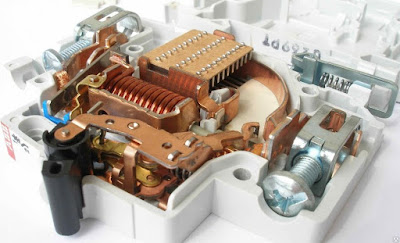
    Unfortunately, even the most perfect wiring or the most expensive electrical equipment will soon show a malfunction or fail. And if the circuit breaker is "knocked out", and after re-enabling the situation is repeated, then a short, but very useful algorithm, given below, will help determine the cause.

Why does the circuit breaker break

Standard circuit breaker (not differential circuit breaker) there are three reasons why it can be knocked out:

  • Prolonged heating of a node or an entire line. Then a thermal release is triggered – a bimetallic plate in the middle of the device.
  • Short circuit. At short circuit, the electromagnetic coil works and the bagger knocks out almost instantly.
  • Due to a malfunction of the device itself. But then the machine can not be turned on at all – the lever is simply not fixed in its place.
If the short – circuit time of the circuit breaker does not exceed a few milliseconds, then a fairly long time interval may pass during heating-several tens of minutes. This data will significantly help with the initial diagnosis.

How to determine the reason why the circuit breaker is triggered

A simple algorithm will help you find the fault:

  1. Determine what kind of machine knocks out. If this is an input device, then most likely the reason for the excessive load is the simultaneous activation of several powerful consumers (hob, boiler, washing machine). Or the reason is in the wiring from the introductory bag to the next group of machines (for example, the wire "breaks" on the body of the shield).
  2. If the machine is not introductory, then you need to determine which line it supplies power to. See what exactly does not work in an apartment or private house when it is disabled.
  3. Replace the triggered device with a known good one.
  4. Turn on the machine and mark the time after which it will work: if almost instantly – a short circuit, after a while-gradual heating.
  5. Disable all consumers of the affected line and re-enable the machine.
  6.  If the bag is knocked out again, you need to check the quality of the connections in the sockets. Very often, it is at the point where the socket is connected that the phase wire comes into contact with the zero one, which gives this effect for the circuit breaker.
  7.  Ð•he Circuit breaker is still knocking out – it's time to move on to checking the junction boxes. Due to poor contact and improper installation, the wires are gradually heated, the insulation is melted, and all the conductors are soldered together.
  8. If the machine still works, the possible reason is the contact of conductors inside the wall. To find the fault in this way, you will need the services of a qualified technician.
A burnt arcing chamber in the machine may cause the device to be triggered incorrectly


Wednesday, May 27, 2020

Why is the "short circuit" not the cause of the fire, but an excuse, and what is the real reason?

       Almost all users with the words "fire" and "electrics", will add the following phrase: «short circuit». Many people are used to awarding a short circuit almost magical power and accusing this physical phenomenon of all imaginable and unthinkable sins. But is it? First, you need to figure out what a short circuit really is.


What is a short circuit?


    A short circuit is a connection between two elements of a circuit (usually conductors) with different potential, or, to put it more simply, voltage. In everyday matters, this is most often the contact of "zero" and "phase", but the short circuit can be between:


  • Two phases. For example, in three-phase networks with a line voltage of 400 V.
  • "Phase" and "earth". Then the ground loop performs its main role-it removes the potential for life-threatening damage.
  • Coils in a coil, transformer, or motor winding.
  • The winding and housing of any electrical device.


The natural consequence of a short circuit is a multiple increase in current. Conductors with a cross section designed for a certain nominal operation are not able to withstand this amount of current, and therefore burn out.


The real danger of a short circuit.


A short circuit is not dangerous because it will burn out the wire, at least in an apartment or private house. In a serious production, where an unexpected break in work can bring millions of losses-Yes, but in homes it will only bring minor discomfort, to eliminate which it is enough to call an electrician. But a short circuit carries another, much more serious danger.

A short circuit, according to the Joule-Lenz law, causes significant heat release, and under other conditions, can cause an electric arc. If the protective automation is selected and installed incorrectly, then in a short period of time, the arc can ignite nearby objects: insulation of neighboring conductors, furniture, interior items, personal belongings. And this is already the source of the fire, which will continue to burn even after the power is cut off in the room.


How do I prevent a short circuit?

In order not to worry about the serviceability of electrical wiring and the integrity of the home, you need to do the following: 

  • For each separate power and lighting line in an apartment or private house, install an automatic switch.
  • Important! Before installing the machine, it is necessary to correctly calculate its nominal value, otherwise the bagger may simply not "see" the short circuit.

  • It is best to mount separate automatic machines on the boiler, hob, and washing machine.
  • If the house is old and "plugs" are installed in the panel, they must be replaced with modern circuit breakers.
  • Check the quality of connections, especially in sockets and junction boxes.

And never ignore the first signs of faulty wiring: sparks, POPs, the smell of burned insulation. Such seemingly insignificant signals can soon lead to a serious fire.

Saturday, May 23, 2020

Green electricity is the cleanest, most beneficial forms of renewable energy

Green power is a subset of renewable energy and represents those renewable energy resources and technologies that provide the highest environmental benefit.  The U.S. voluntary market defines green power as electricity produced from solar, wind, geothermal, biogas, eligible biomass, and low-impact small hydroelectric sources. Customers often buy green power for its zero emissions profile and carbon footprint reduction benefits.

What is green electricity?
Green electricity is the cleanest, most beneficial forms of renewable energy. For example, municipal solid waste or large scale hydropower are indeed renewable but still have major polluting capacity. These are the energy sources considered to provide green electricity:

This article is more than 3 years old Renewables made up half of net electricity capacity added last year

Green energy accounted for more than half of net electricity generation capacity added around the world last year for the first time, leading energy experts have found.

The International Energy Agency (IEA) said the milestone was evidence of a rapid transformation in energy taking place, and predicted capacity from renewable sources will grow faster than oil, gas, coal or nuclear power in the next five years.

Thursday, May 21, 2020

Key Components of an All-Electric Car

Battery (all-electric auxiliary): In an electric drive vehicle, the auxiliary battery provides electricity to power vehicle accessories.

Charge port: The charge port allows the vehicle to connect to an external power supply in order to charge the traction battery pack.
DC/DC converter: This device converts higher-voltage DC power from the traction battery pack to the lower-voltage DC power needed to run vehicle accessories and recharge the auxiliary battery.
Electric traction motor: Using power from the traction battery pack, this motor drives the vehicle's wheels. Some vehicles use motor generators that perform both the drive and regeneration functions.
Onboard charger: Takes the incoming AC electricity supplied via the charge port and converts it to DC power for charging the traction battery. It monitors battery characteristics such as voltage, current, temperature, and state of charge while charging the pack.
Power electronics controller: This unit manages the flow of electrical energy delivered by the traction battery, controlling the speed of the electric traction motor and the torque it produces.
Thermal system (cooling): This system maintains a proper operating temperature range of the engine, electric motor, power electronics, and other components.
Traction battery pack: Stores electricity for use by the electric traction motor.
Transmission (electric): The transmission transfers mechanical power from the electric traction motor to drive the wheels.